
Will we touch upon such an important topic in this article? as in “colors of wires in electrical wiring.” Let's look at various aspects of this topic, ranging from standard color codes to practical tips for installing and using electrical wiring safely.
Why do we need color coding for wires and cables?
Content
- Why do we need color coding for wires and cables?
- Colors of wires in electrics: where are the phase, neutral and ground
- Phase color
- Color of zero (neutral conductor)
- Ground wire color
- Designation of colors on electrical diagrams
- Wire marking for 3-phase and DC electrical networks
- Manual color marking
- Marking of two-core wires
- Marking three-wire wires
- Letter designation of wires
- How to check the correctness of labeling in an apartment
- What to do if all the wires in the cable have the same color insulation

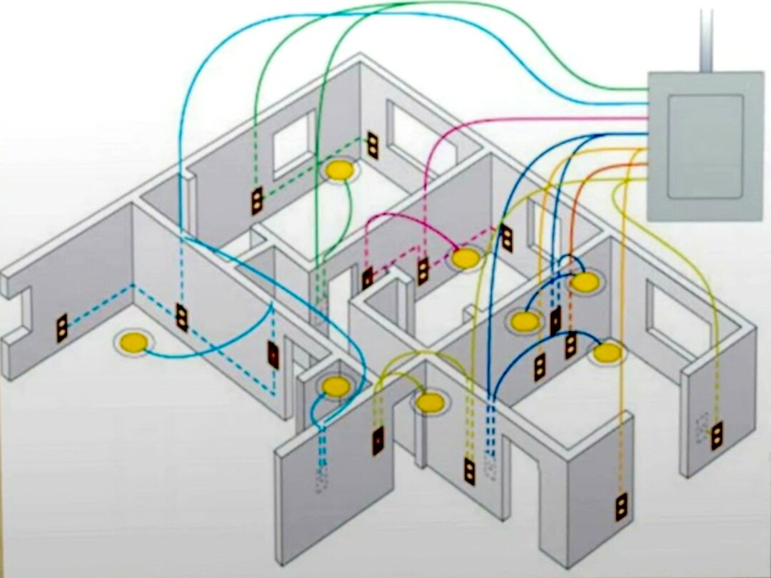
Proper wire assignment plays a very important role in electrical wiring. It is a system in which each cable color has its own specific function and designation. This is what electricians use to navigate.
There are acceptable colors that are established by standards and regulations to ensure protection and simplify the installation and maintenance of electrical wiring.
Colors of wires in electrics: where are the phase, neutral and ground

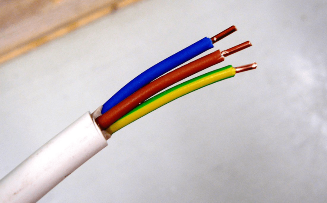
Each wire is identified by its own color coding. As a rule, the phase wire is placed under red, black or brown insulation. Zero is indicated only by a light blue tint or blue, and grounding is indicated by a green or yellow coated wire.
Phase color

According to the standards, the phase is connected with a brown conductor, but markings in a different color are also acceptable. If your network has several phases, in addition to color marking, letter marking may be used. Typically marked with the letter "L". If there is more than one phase, they will be marked “L1”, “L2”, “L3” or A, B and C.
Color of zero (neutral conductor)
According to GOST in Russia, zero is any shade of blue that can be supplemented with a white stripe. It is marked as “N”. Other shades of current-carrying conductors cannot be used to connect the neutral conductor.
Ground wire color

They are exclusively green in color and complemented by a yellow line. The letters indicate "PE". Knowing the color codes, it is much easier to figure out which cable is which in the wiring.
At the same time, it is not wise to unconditionally trust this knowledge, because not all electricians adhere to the rules.
Designation of colors on electrical diagrams
The project determines which shades and how many of them will be used in practice. Generally accepted standards: phase - red, ground - yellow, zero - blue. If the network contains several phases, they may be marked in green or black.
In a network with one phase, one color is used, but if more massive networks are designed, then the phase can be marked in both black and green. If there is a branch from a network with one phase, it is marked with the same shade.
Wire marking for 3-phase and DC electrical networks

When designing and installing a 3-phase alternating current network, high-voltage inputs are colored by phase:
- “A” – yellow;
- “B” – green;
- "C" is red.
Manual color marking
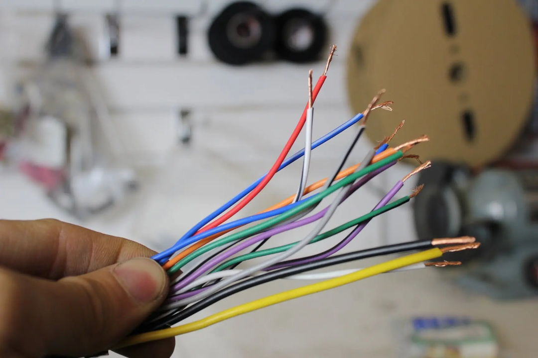
This shade identification is used in situations where it is necessary to work with wires of a single shade during installation. This need arises when working in houses where electrical wiring was installed before standards were developed. The places where manual identification is used are determined by the PUE norms and GOST standards. Marking is usually done on the ends of the wires where they are connected using a bus.
Marking of two-core wires
When the cable is connected to the network, a screwdriver with a light indicator is used to identify the phase wires. This screwdriver only works on two-wire wires, since in the case of multiple phases it becomes more difficult to determine which phase the indicator belongs to. Under these conditions, the function of each wire is determined using a multimeter.
Next, you need a set of heat shrink tubing or electrical tape to mark the wires. The number of colors used depends on the scheme that needs to be indicated. But according to the standard, the phase is marked in red. You cannot mark it with green, yellow, or blue colors. Markings are made at the joints.
Marking three-wire wires

To determine the functionality in three-wire wires, take a multimeter. The device measures alternating voltage, after which the electrician, using probes, needs to touch the phase wire and others in series. The combination of phase and zero will give higher performance than phase and grounding. After determining zero and phase, apply markings. Grounding is indicated in green, zeros in blue, phase in any other color.
Letter designation of wires
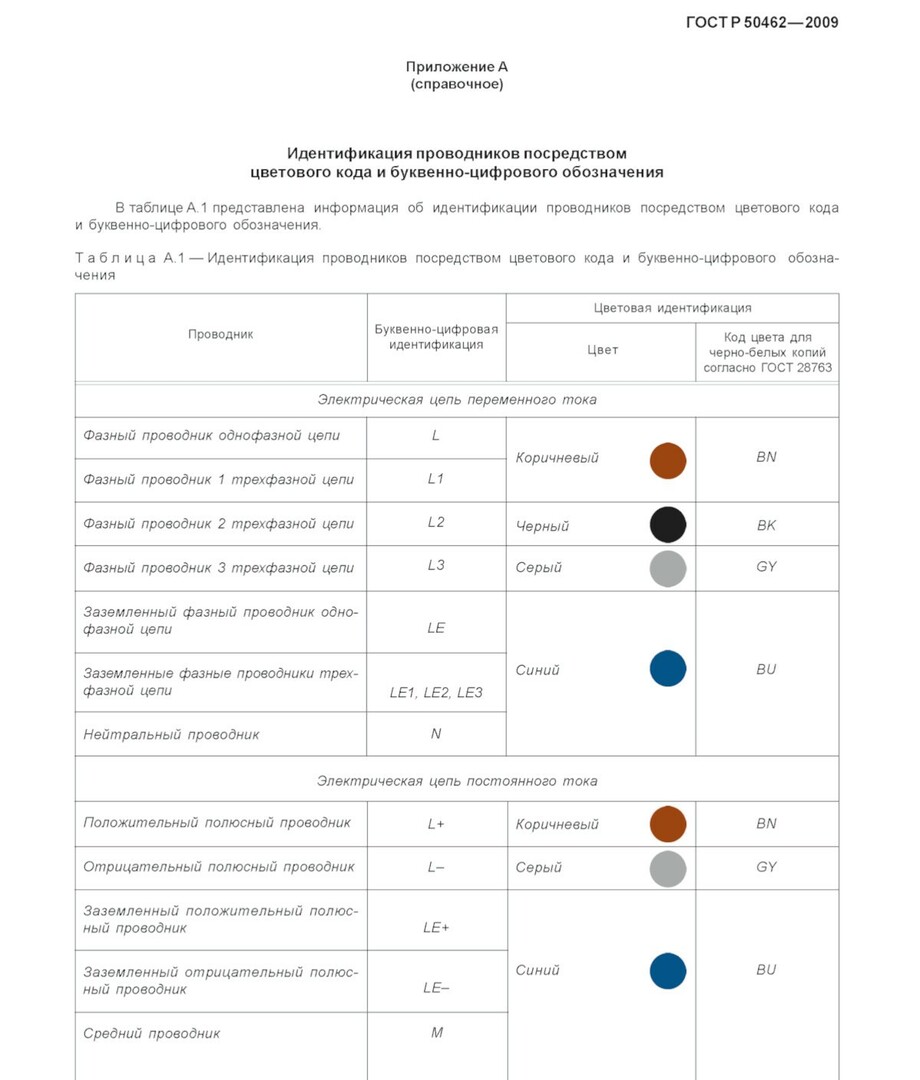
In our country, GOST R 50462 of 2009 is in force.
How to check the correctness of labeling in an apartment

Before starting work, make sure that the markings are correct. Use a screwdriver with an indicator, a tester or a multimeter for this.
What to do if all the wires in the cable have the same color insulation
To determine their function, you will need to test with a multimeter.

To do this, you need to set the multimeter to AC voltage measurement mode (turn off the mains).
Connect the multimeter between the two cables.
Turn on the power and pay attention to the multimeter readings. Phase, neutral and ground have different voltage values, which can be detected by a multimeter.
- Phase: When between phase and neutral or phase and ground, the multimeter will show voltage.
- Zero: If the multimeter reading is zero, it means that the cables are connected to the neutral wire.
- Grounding: If the multimeter shows voltage near zero and it drops, then this indicates the presence of ground in the cable being tested.
When installing new electrical wiring, it is important to follow the generally accepted color markings. When working with old wiring where the colors do not match the standards, use an indicator screwdriver to determine the phase. Wires must be laid horizontally and vertically.


